In 1913, the D&IR gave an order to the Baldwin Locomotive Works for 4 "Mikado" type locomotives and it also gave the Lima Locomotive Works an order for two of the same. The six 2-8-2s arrived in 1913 and were designated as Class N with the four that Baldwin-built assigned road numbers 300-303 and the two Lima-built were given numbers 304 and 305. These locomotives had 54" drivers, 27" x 30" cylinders, a 170 psi boiler pressure, they exerted 58,522 pounds of tractive effort and each weighed 287,600 pounds. The firebox was 271 square feet, the evaporative heating surface was 4,108 square feet and with the superheater the combined heating surface was 4,948 square feet.
Three more 2-8-2s were added to the D&IR roster in 1916. This Lima built group was designated as Class N-1 and were numbered 306-308. They had 58" drivers, 27" X 30" cylinders, a 185 psi boiler pressure and exerted 59,250 pounds of tractive effort and each weighed 294,000 pounds. The firebox was 268 square feet, the evaporative heating surface was 4,453 square feet and with the superheater the combined heating surface was 5,539 square feet.
Another three "Mikados" were delivered from Baldwin in 1923. They were designated as Class N-2 with roads numbers 309 through 311 assigned. These locomotives were very similar to the Class N-1 locomotives delivered in 1916. They were 44,320 pounds heavier but the firebox and heating surfaces were almost identical. .
The two railroads were operated independently, but in 1930 they combined their rosters of the motive power. The locomotives of the D&IR were renumbered simply by adding a numeral "1", as a prefix, to all existing road numbers. In 1937, the D&IR and the DM&NR were consolidated with the Spirit Lake Transfer Railway and the combined railroad was named Duluth, Missabe & Iron Range Railway.
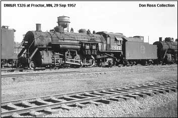
By the late 1950s, most railroads had converted to diesels, but the DM&IR wanted to continue with steam and in 1948 it bought 26 "Mikados" from another US Steel owned railroad, the Elgin, Joliet & Eastern. These locomotives were divided into three classes, Class N-4, all built by ALCO (road numbers 1312-1321), Class N-5, all built by Lima (road numbers 1322-1325) and Class N-6, all built by Baldwin (road numbers 1326-1337). They were similar and had 63" drivers, 28" x 30", a 200 psi boiler pressure and exerted 63,467 pound of tractive effort.
There is one surviving D&IR 2-8-2 "Mikado" type locomotive. It is a Class N-6, number 1330, which was ex EJ&E number 765. This locomotive is on display at City Hall at the corner of Rte 20 and Rte 53 in Gary, IN.
| Class | Qty. | Road Numbers | DM&IR Numbers | From Other RR | Yr. Acquired | Year Built | Builder | Notes |
|---|---|---|---|---|---|---|---|---|
| N | 4 | 300-303 | 1300-1303 | 1913 | Baldwin | 1 | ||
| N | 2 | 304-305 | 1304 & 1305 | 1913 | Lima | 2 | ||
| N-1 | 3 | 306-308 | 1306-1308 | 1916 | Baldwin | 3 | ||
| N-2 | 3 | 309-311 | 1309-1311 | 1923 | Baldwin | 4 | ||
| N-4 | 10 | 1312-1321 | EJ&E | 1948 | 1923 | ALCO | 5 | |
| N-5 | 4 | 1322-1325 | EJ&E | 1948 | 1923 | Lima | 6 | |
| N-6 | 12 | 1326-1337 | EJ&E | 1948 | 1929-30 | Baldwin | 7 |
See data from DM&IR 6 -1951 Locomotive Diagrams supplied in May 82005 by Allen Stanley from his extensive Rail Data Exchange. See also DeGolyer, Volume 46, pp. 289+, and "Mikado and Pacific Locomotives for the Duluth and Iron Range," Railway and Locomotive Engineering, Volume 26, No 8 (August 1913), pp. 280-281. (Many thanks to Chris Hohl for his 27 August 2015 email and spreadsheet spelling out the Baldwin specs for all three orders of D&IR Mikados. It led to the addition of three new entries and revision of 7288-7290.).
When the Iron Range went to Mikados a few years after it bought 8its last Consolidations, it didn't pussy-foot. These 2-8-2s ranked with the largest of the 8time, particularly in the grate and firebox areas. The latter included 37.3 sq ft (398.19 sq m) in five American Arch Company tubes. The cylinders received their steam through 15" (381 mm) piston valves. The R&LE report notes that the back equalizing beams were placed diagonally to connect directly with the truck spring links.Other details allowed the removal of cross beams and allowed "ample room" for the ash pan. Beginning in 1931, the DM&IR significantly modified this quartet; see Locobase 16191.Data from DM&IR 6 -1951 Locomotive Diagrams supplied in May 2005 by Allen Stanley from his extensive Rail Data Exchange. (Many thanks to Chris Hohl for his 27 August 2015 email and spreadsheet spelling out the Baldwin specs for all three orders of D&IR Mikados. It led to the addition of three new entries and revision of 7288-7290.).
As noted in Locobase 7288, later DM&IR upgrades begun in 1931 significantly altered the specifications of these locomotives. Tube count decreased by 15 to 273 and firebox heating surface area to the 271 sq ft shown. This wasn't an unusual change. What was not common, however, was to trade tube count for an increasd diameter (from 5 3/8" to 5 1/2") in the flues. Even with the increase in flue diameter, the superheater area decreased by 59 sq ft (5.48 sq m), which suggests either shorter or perhaps thinner superheater elements. Even tender capacities decreased. In those same upgrades, however, boiler pressure increased by 25 psi (1.72 bar) and adhesion weight showed a 15 1/2 ton increase over the 1913 specification (which was not necessarily its delivered weight). As with the Lima engines shown in Locobase 16190, the original 1913 Baldwins may have had difficulty getting enough steam in the cylinders because the piston valve diameter increased to 16" (406 mm). Still later, both 1300 and 1302 were fitted with Security circulators in the firebox. Like most of the DM & IR engines, these Mikados remained in service until the road went to diesels in the late 1950s.Data from DM&IR 6 -1951 Locomotive Diagrams supplied in May 2005 by Allen Stanley from his extensive Rail Data Exchange. (Many thanks to Chris Hohl for his 27 August 2015 email and spreadsheet spelling out the Baldwin specs for all three orders of D&IR Mikados. It led to the addition of three new entries and revision of 7288-7290.). Lima works numbers were 1311-1312 in December 1913.
Locobase 7288 shows the first four Duluth & Iron Range Mikados delivered by Baldwin in 1913. The Lima pair were only the sixth and seventh Mikes delivered by that Ohio builder. Locobase has not found data for the original configuration, showing here instead the upgrades adopted beginning in 1931. They were very similar to those installed in the Baldwins (Locobase 16191), but somehow the superheater area reduction was limited to 29 sq ft (2.69 sq m). The original 1913 design may have had difficulty getting enough steam in the cylinders because the piston valve diameter increased to 16" (406 mm). Later, 1305's firebox received Security circulators.See data from DM&IR 6 -1951 Locomotive Diagrams supplied in May 2005 by Allen Stanley from his extensive Rail Data Exchange. See also DeGolyer, Volume 55, pp. 177+. (Many thanks to Chris Hohl for his 27 August 2015 email and spreadsheet spelling out the Baldwin specs for all three orders of D&IR Mikados. It led to the addition of three new entries and revision of 7288-7290.).Works numbers were 43303-43305 in May 1916.
Three years after Baldwin and Lima supplied the Iron Range with its first Mikados (Locobase 7288), Baldwin delivered three more slightly bigger engines. The firebox stayed the same, but the boiler had more tubes and flues, which yielded a higher percentage of superheated heating surface. Steam admission came through 15" (381 mm) piston valves. Otherwise, there were few differences. The Mikes went through a makeover at some later stage that seems to involved a new boiler pressed to 200 psi. The boiler's tube count was reduced by sixteen to 288, which reduced the evaporative heating surface area to 4,453 sq ft (413.85 sq m) and two of five arch tubes were also deleted, trimming the firebox heating surface to 268 sq ft (24.9 sq m). The 1951 diagram gives the adhesion weight as a considerable 251,270 lb (113,974 kg) and overall engine weight as 338,320 lb (153,460 kg), which put the factor of adhesion at 3.9.See data from DM&IR 6 -1951 Locomotive Diagrams supplied in May 2005 by Allen Stanley from his extensive Rail Data Exchange. (Many thanks to Chris Hohl for his 27 August 2015 email and spreadsheet spelling out the Baldwin specs for all three orders of D&IR Mikados. It led to the addition of three new entries and revision of 7288-7290.).
The Mikes described in Locobase 7289 and 7290 went through a makeover at some later stage that seems to involved a new boiler pressed to 200 psi. In all six, the boiler's tube count was reduced by sixteen to 288. Two of five arch tubes were also deleted, trimming the firebox heating surface. As with the Baldwins shown in Locobase 16190, reducing the number of tubes in the boiler allowed an increase in flue diameter from 5 3/8" to 5 1/2". The shops later installed two Nicholson syphons in 1308's firebox while fitting Security circulators in 1306.See data from DM&IR 6 -1951 Locomotive Diagrams supplied in May 2005 by Allen Stanley from his extensive Rail Data Exchange. See also DeGolyer, Volume 71, pp. 65+. (Many thanks to Chris Hohl for his 27 August 2015 email and spreadsheet spelling out the Baldwin specs for all three orders of D&IR Mikados. It led to the addition of three new entries and revision of 7288-7290.).Works numbers were 56507-56509.
Soon after the First World War, the Iron Range returned to Baldwin for more Mikados. Rather than adopting the USRA Heavy Mikado (Locobase 41) design, the Iron Range accepted a slight rework of the 1916 Mikes they already operated (see Locobase 7289). A principal reason may have been the need to have smaller drivers than the USRA's 63" and the railroad was quite familiar with the peculiarities of this design. The 1923 trio was delivered with the same tube count as the 1916 engines, but later had the count reduced to 291 resulting in a reduction of the evaporative heating surface to the 4,484 sq ft shown in the specifications. One difference was the provision of a Superheater Company (Elesco) feed water heater. Steam was admitted to the cylinders through 15" (381 mm) piston valves. In any case, all of the engines served to the end of steam power on the DM & IR.
Principal Dimensions by Steve Llanso of Sweat House Media | |||||
|---|---|---|---|---|---|
| Class | N | N - modified | N-1 | N-2 | N-2/N-3 - updated |
| Locobase ID | 7288 | 16191 | 16190 | 7289 | 16192 |
| Railroad | Duluth & Iron Range (DM&IR) | Duluth & Iron Range (DM&IR) | Duluth & Iron Range (DM&IR) | Duluth & Iron Range (DM&IR) | Duluth & Iron Range (DM&IR) |
| Country | USA | USA | USA | USA | USA |
| Whyte | 2-8-2 | 2-8-2 | 2-8-2 | 2-8-2 | 2-8-2 |
| Number in Class | 4 | 5 | 2 | 3 | 6 |
| Road Numbers | 300-303/1300-1303 | 1300-1303 | 304-305/1304-1305 | 306-308/1306-1308 | 1306-1311 |
| Gauge | Std | Std | Std | Std | Std |
| Number Built | 4 | 2 | 3 | ||
| Builder | Baldwin | DM&IR | Lima | Baldwin | DM&IR |
| Year | 1913 | 1931 | 1913 | 1916 | 1931 |
| Valve Gear | Walschaert | Walschaert | Walschaert | Walschaert | Walschaert |
| Locomotive Length and Weight | |||||
| Driver Wheelbase (ft / m) | 15.75 / 4.80 | 15.75 / 4.80 | 15.75 / 4.80 | 15.75 / 4.80 | 15.75 / 4.80 |
| Engine Wheelbase (ft / m) | 33.67 / 10.26 | 35 / 10.67 | 34.83 / 10.62 | 35 / 10.67 | 35 / 10.67 |
| Ratio of driving wheelbase to overall engine wheelbase | 0.47 | 0.45 | 0.45 | 0.45 | 0.45 |
| Overall Wheelbase (engine & tender) (ft / m) | 68.90 / 21 | 70.37 / 21.45 | 70.23 / 21.41 | 70.37 / 21.45 | 70.37 / 21.45 |
| Axle Loading (Maximum Weight per Axle) (lbs / kg) | |||||
| Weight on Drivers (lbs / kg) | 220,000 / 99,790 | 251,270 / 113,974 | 251,270 / 113,974 | 230,000 / 104,326 | 251,270 / 113,974 |
| Engine Weight (lbs / kg) | 290,000 / 131,542 | 338,320 / 153,460 | 338,320 / 153,460 | 296,000 / 134,264 | 338,320 / 153,460 |
| Tender Loaded Weight (lbs / kg) | 166,000 / 75,296 | 159,500 / 72,348 | 167,600 / 76,022 | 161,100 / 73,074 | 161,100 / 73,074 |
| Total Engine and Tender Weight (lbs / kg) | 456,000 / 206,838 | 497,820 / 225,808 | 505,920 / 229,482 | 457,100 / 207,338 | 499,420 / 226,534 |
| Tender Water Capacity (gals / ML) | 9000 / 34.09 | 8260 / 31.29 | 8560 / 32.42 | 8260 / 31.29 | 8260 / 31.29 |
| Tender Fuel Capacity (oil/coal) (gals/tons / Liters/MT) | 14 / 13 | 13 / 12 | 15.80 / 14 | 13 / 12 | 13.80 / 13 |
| Minimum weight of rail (calculated) (lb/yd / kg/m) | 92 / 46 | 105 / 52.50 | 105 / 52.50 | 96 / 48 | 105 / 52.50 |
| Geometry Relating to Tractive Effort | |||||
| Driver Diameter (in / mm) | 58 / 1473 | 58 / 1473 | 58 / 1473 | 58 / 1473 | 58 / 1473 |
| Boiler Pressure (psi / kPa) | 175 / 12.10 | 200 / 13.80 | 200 / 13.80 | 185 / 12.80 | 200 / 13.80 |
| High Pressure Cylinders (dia x stroke) (in / mm) | 27" x 30" / 686x762 | 27" x 30" / 686x762 | 27" x 30" / 686x762 | 27" x 30" / 686x762 | 27" x 30" / 686x762 |
| Tractive Effort (lbs / kg) | 56,089 / 25441.57 | 64,102 / 29076.21 | 64,102 / 29076.21 | 59,294 / 26895.34 | 64,102 / 29076.21 |
| Factor of Adhesion (Weight on Drivers/Tractive Effort) | 3.92 | 3.92 | 3.92 | 3.88 | 3.92 |
| Heating Ability | |||||
| Tubes (number - dia) (in / mm) | 289 - 2" / 51 | 273 - 2" / 51 | 273 - 2" / 51 | 304 - 2" / 51 | 288 - 2" / 51 |
| Flues (number - dia) (in / mm) | 38 - 5.375" / 146 | 38 - 5.5" / 140 | 38 - 5.5" / 140 | 45 - 5.375" / 137 | 45 - 5.5" / 140 |
| Flue/Tube length (ft / m) | 19.42 / 5.92 | 19.42 / 5.92 | 19.42 / 5.92 | 19.42 / 5.92 | 19.42 / 5.92 |
| Firebox Area (sq ft / m2) | 289.30 / 26.88 | 271 / 25.18 | 272 / 25.27 | 281.50 / 26.15 | 268 / 24.90 |
| Grate Area (sq ft / m2) | 74.60 / 6.93 | 74.60 / 6.93 | 74.60 / 6.93 | 74.60 / 6.93 | 74.60 / 6.93 |
| Evaporative Heating Surface (sq ft / m2) | 4249 / 391.30 | 4108 / 381.64 | 4109 / 381.74 | 4583 / 425.77 | 4453 / 413.69 |
| Superheating Surface (sq ft / m2) | 899 / 83.52 | 840 / 78.04 | 870 / 80.82 | 1086 / 100.89 | 1086 / 100.89 |
| Combined Heating Surface (sq ft / m2) | 5148 / 474.82 | 4948 / 459.68 | 4979 / 462.56 | 5669 / 526.66 | 5539 / 514.58 |
| Evaporative Heating Surface/Cylinder Volume | 213.73 | 206.64 | 206.69 | 230.53 | 223.99 |
| Computations Relating to Power Output (More Information) | |||||
| Robert LeMassena's Power Computation | 13,055 | 14,920 | 14,920 | 13,801 | 14,920 |
| Same as above plus superheater percentage | 15,274 | 17,456 | 17,456 | 16,423 | 17,904 |
| Same as above but substitute firebox area for grate area | 59,234 | 63,414 | 63,648 | 61,972 | 64,320 |
| Power L1 | 11,731 | 12,665 | 12,933 | 14,181 | 15,139 |
| Power MT | 470.23 | 444.49 | 453.89 | 543.72 | 531.31 |
Principal Dimensions by Steve Llanso of Sweat House Media | |
|---|---|
| Class | N-3 |
| Locobase ID | 7290 |
| Railroad | Duluth & Iron Range (DM&IR) |
| Country | USA |
| Whyte | 2-8-2 |
| Number in Class | 3 |
| Road Numbers | 309-311/1309-1311 |
| Gauge | Std |
| Number Built | 3 |
| Builder | Baldwin |
| Year | 1923 |
| Valve Gear | Walschaert |
| Locomotive Length and Weight | |
| Driver Wheelbase (ft / m) | 15.75 / 4.80 |
| Engine Wheelbase (ft / m) | 35 / 10.67 |
| Ratio of driving wheelbase to overall engine wheelbase | 0.45 |
| Overall Wheelbase (engine & tender) (ft / m) | 70.37 / 21.45 |
| Axle Loading (Maximum Weight per Axle) (lbs / kg) | |
| Weight on Drivers (lbs / kg) | 240,000 / 108,862 |
| Engine Weight (lbs / kg) | 320,000 / 145,150 |
| Tender Loaded Weight (lbs / kg) | 161,100 / 73,074 |
| Total Engine and Tender Weight (lbs / kg) | 481,100 / 218,224 |
| Tender Water Capacity (gals / ML) | 8260 / 31.29 |
| Tender Fuel Capacity (oil/coal) (gals/tons / Liters/MT) | 13 / 12 |
| Minimum weight of rail (calculated) (lb/yd / kg/m) | 100 / 50 |
| Geometry Relating to Tractive Effort | |
| Driver Diameter (in / mm) | 58 / 1473 |
| Boiler Pressure (psi / kPa) | 185 / 12.80 |
| High Pressure Cylinders (dia x stroke) (in / mm) | 27" x 30" / 686x762 |
| Tractive Effort (lbs / kg) | 59,294 / 26895.34 |
| Booster (lbs) | 11,000 |
| Factor of Adhesion (Weight on Drivers/Tractive Effort) | 4.05 |
| Heating Ability | |
| Tubes (number - dia) (in / mm) | 304 - 2" / 51 |
| Flues (number - dia) (in / mm) | 45 - 5.375" / 137 |
| Flue/Tube length (ft / m) | 19.42 / 5.92 |
| Firebox Area (sq ft / m2) | 279 / 25.92 |
| Grate Area (sq ft / m2) | 74.60 / 6.93 |
| Evaporative Heating Surface (sq ft / m2) | 4580 / 425.49 |
| Superheating Surface (sq ft / m2) | 1072 / 99.59 |
| Combined Heating Surface (sq ft / m2) | 5652 / 525.08 |
| Evaporative Heating Surface/Cylinder Volume | 230.38 |
| Computations Relating to Power Output (More Information) | |
| Robert LeMassena's Power Computation | 13,801 |
| Same as above plus superheater percentage | 16,423 |
| Same as above but substitute firebox area for grate area | 61,422 |
| Power L1 | 14,054 |
| Power MT | 516.40 |