The Pennsylvania Railroad GG1: The Pantograph
The pantograph is a diamond - shapped device mounted on the roof of the GG1 (and other electric locomotives) to permit current from the overhead 11,000 Volt AC cantenary contact wire to be collected to feed the traction motors.
The height of the overhead conductor ranges from a minimum of 16' - 10" to a maximum of 25' - 0" and the pantograph is hinged and spring loaded to permit it to colapse and expand to compansate for the variations in height and to allow its pick-up shoe to maintain good contact with the conductor.
The diamond - shapped framework consists of four movable sections of tubular steel members hinged together and secured to two length of angle iron. The framework consists of four movable sections, two upper and two lower. The two upper sections are hinged together at the top and hinged to the lower sections which in turn are fastened through hinges to the length of angle iron. Each section is assembled from high carbon steel tubing and cast fittings to form a rectangle with diagonal cross bracing through an "X" shapped center fittig. The entire assembly is mounted on four insulators. The insulators are made up of two porcelain petticoats placed one on top of the other and cemented to a vetical pin fastened to a wide steel plate that is bolted to the roof. The angle iron bases are bolted to a steel cap placed on top of the insulators.
The contact shoe is made up of flat steel 4" wide and 1/2" thick and it is mounted just above the top hinges. Downward curving horns are fitted at each side of the shoe to prevent snagging of the contact wire at crossovers.
The pantograph can be lowered by air pressure and when it is lowered it is held down by a latch which catches a crossmember of the upper framework. The latch can be unlocked by air pressure and when the latch is released the pantograph is raised by the springs.
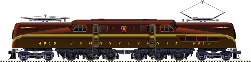
The GG1 was equipped with two pantograph, but only one needed to be raised to operate the locomotive, because they were jumpered together and connected to the on board transformer through a common current path. The usual practice was to operate with the forward pantograph in the locked down position and with the rear one raised. This practice was adopted because if the raised rear pantograph was struck or came apart the one in front could be used, but if the one in front was raised and it fell apart it could render the rear one inoperable.