Steam Locomotive Tenders

By the mid-1800s most steam locomotive tenders consisted of a fuel bunker (that held coal or wood) surrounded by a "U" shaped (when viewed from the top) water jacket. The overall shape of the tender was usually rectangular. The bunker which held the coal was sloped downwards toward the locomotive providing easier access to the coal.
The ratio of water to fuel capacities of tenders was normally based on two water-stops to each fuel stop because water was more readily available than fuel. One pound of coal could turn six pounds of water (0.7 gallons) to steam. Therefore, tender capacity ratios were normally close to 14 tons of coal per 10,000 gallons of water. One exception to this were the NYC tenders which were designed to pick up water at speed from track pans. These tenders had a much larger coal to water ratio.

Other factors which determined the size of tenders were turntable length. Some railroads bought large locomotives with small tenders so that they could still be turned on their existing turntables. In many cases, these tenders were replaced with larger ones as larger turntables became available. Construction styles also determined tender size. In 1927 the first solid steel cast tender frame made it possible to attach a single large tank called a "water bottom". These tenders could hold 1,500 to 2,000 more gallons of water then previous tenders.
There were a number of variations of tender design. This page will describe a few of them.
Slopeback Tenders

Typical switch engines spent as much time waiting as they did switching. They didn't require large tenders. Tenders for such locomotives were designed with a sloping rear -- reducing the capacity for water, but allowing better visibility to the rear which was very important during switching operations. The Pennsylvania Railroad (and many others) had many switchers with slopeback tenders.
Whaleback Tenders

During the early days of Mallet and articulated locomotives, whale-back (sometimes called "turtle back") tenders were used. Whaleback tenders consisted of two separate tanks (the leading one for oil, the aft one for water). They had greater capacity than the old square tanks. They looked like a half cylinder laying on its side. They were some of the ugliest tenders. Many early Southern Pacific cab-forwards used whale-back tenders.
Photos
Vanderbilt Tenders

A round tank has several advantages over a rectangular tank.
- A round tank holds more than a rectangular tank of the same surface area.
- A round tank (a cylinder) is stronger than a rectangular tank (a box).
- A round tank is lighter than a rectangular tank of the same capacity (partially because a rectangular tank requires a great deal of internal bracing).
On May 31, 1901, a patent was issued to Cornelius Vanderbilt for a tender with a cylindrical water tank (Cornelius was the great grandson of the Commodore). Some railroads went for Vanderbilt tenders in a big way. Others did not. Railroads that adopted the Vanderbilt style tender for many of their steam locomotives include:
- Baltimore & Ohio
- Canadian National
- Grand Trunk Western
- Great Northern
- Southern Pacific
- Union Pacific
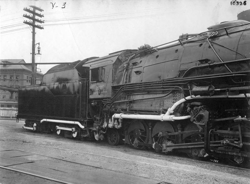
Seven of the B&O T-3 class 4-8-2s, built by the road between 1943 to 1948, were retro fitted with large vanderbilt tenders, mounted on six wheel trucks. It is conceivable that these tenders were salvaged from scrapped locomotives. The B&O was a large user of Vanderbilt tenders. They had some very odd ones which had three four-wheel trucks, rather than two six-wheel. These may have been applied to 2-8-8-0 engines.
Photos
- GN Vanderbilt Tender from 4-8-4 2575 (Photo courtesy R. Glueck) (more information on this tender)
Long Haul Tenders

The PRR made good use of "long haul" tenders. The PRR long haul tenders generally had two 8-wheel trucks giving them one more axle than a centipede tender. The T class 4-4-4-4 duplex locomotives were equipped with Class 180-P-84 tenders that carried 19,200 gallons of water and 42.5 tons of coal (221 tons total weight). The S-1 class 6-4-4-6 duplex locomotive was equipped with the same class tender but with 24,230 gallons of water and 26 tons of coal capacity.
The AT&SF 2900 Class also used long haul tenders with 8-wheel "Buckeye" trucks. Their tender capacity was 24,500 gallons of water and 7,000 gallons of fuel oil.

Photos
Centipede Tenders

The centipede tender was introduced in the late 1930s. What gives this style of tender its name is the number of wheels it uses. A centipede tender is rigidly mounted to five axles (ten wheels) which are allowed to move laterally. There is also a four-wheel leading truck that is able to swivel, for a grand total of 14 wheels.
This tender is also sometimes referred to as a "pedestal" tender because of the shape of the frame holding the container -- slightly smaller at the bottom which had a "pedestal" frame supported by the five rigid axles. The actual shape of the tank was semi-cylindrical. This design takes advantage of both rectangular and cylindrical tank shapes, with a rounded top and bottom of the tank sides maximizing strength and reducing materials and weight.
The centipede tenders used on the Big Boys used a Nathan DV-7 mechanical lubricator that was driven by the stoker engine. It was used to lubricate various points of friction including the axle bearing box pedestal wear faces and the front truck center pin. The box for the lubricator and other related accommodations fit entirely inside the stoker engine compartment.
The Big Boy centipede tenders were designed so that they could haul a 3600 ton train from Ogden to Echo (40 miles) without stopping. This required 24,000 gallons of water and 28 tons of coal. The second series of Big Boys were equipped with 25,000 gallon/28 ton tenders which were originally designed for the 1942 Challengers. The difference between the 25-C-1 (nominal 25,000 gallons, C=cylindrical) and the 25-C-2 through 5 tanks was where the fuel bunker side slope sheet joined the outer skin. With a sufficient number of photographs one can see that the early tank had that side slope sheet joining the tank outer skin about 2-feet below the upper radius of the bunker. On the later tenders that slope sheet joined the side sheet immediately below the bunker top radius. Adding a little to the confusion for many about the Big Boy tenders was the fact that 25-C-1 and 25-C-4 tenders were completely interchangeable and were traded between both groups of Big Boys, for convenience. The rivets used along the top edge of the slope sheet had a large button head and are fairly easy to see in photos that were typically taken from a forward angle.
Centipede tenders were used on locomotives that had enormous fuel requirements. These locomotives included:
- Boston & Maine Mountains
- Denver & Rio Grande L-97 Challengers
- Duluth, Missabe & Iron Range Yellowstones
- Clinchfield E-2, E-3 Challengers
- Great Northern Z-6 Challengers?
- New York Central Niagaras
- New York Central Hudsons (Class J-1a 5266-5274 at times, Class J-3a after 1944, 5426 photo, more photos)
- Northern Pacific A-5 Northerns
- Northern Pacific Z-7 and Z-8 Challengers
- Spokane, Portland & Seattle Z-6 Challengers?
- Union Pacific Big Boy
- Union Pacific Challenger
- Union Pacific FEF-2,3 Series
Photos
- DM&IR Yellowstone photos
- UP 3985 tender (photo taken at San Bernardino, Aug 20, 2000 courtesy David Roberts)
No Tenders (Tank Locomotives)

Small switch engines that were only operated in a yard close to a fueling site didn't need a tender. Instead, they carried a "U" shaped water tank that was draped over the boiler and a small bunker behind the cab for coal or oil. These were called tank engines. Sometimes the water tank was split in two and were on either side of the boiler.
A "T" is added to the Whyte system of wheel classifications to denote a tank locomotive. For example, an 0-6-0 would be a normal switch engine with a tender. An 0-6-0T would be a switch engine with a "tank" instead of a tender. Sometimes 0-6-0ST was used. The "ST" stood for Saddle Tank. Sometimes, a tender was added to a tank engine to provide extra range. This type of configuration was denoted by 0-6-0T-T.
Forney or "rear tank" type locomotives sometimes went under the designation of 0-4-4RT. The "RT" of course stood for Rear Tank.
There is another type of tank engine arrangement not typically found on North American built engines (but very common on European built ones). This would be a "Well Tank" locomotive. The water was carried in a tank built into the frame of the locomotive. Usually these were small narrow gauge switchers. An 0-4-0 example would carry the designation 0-4-0WT. The popular LGB German 0-4-0 G scale engine is a model of one of these Well Tank locomotives.
Photos
- Saddle Tank Locomotives
- American Brake Shoe & Foundry 1 (Colorado Fuel & Iron #3)
- Deloro Mining 46 (Photo by Ken Jones)
- Un-identified 0-4-0ST (Photo by Michael Castellow)
- Wanamaker, Kempton & Southern 2
- Saddle Tank + Tender Locomotives
- Side Tank Locomotives
- Plant McDonough 97 (Photo by Eric Louterbach)
- Fiesta Texas 502 (Photo by Justice Delacruz)
- US Navy 3
- Rear Tank Locomotives
- Belle Point & Reserve RR #1
- NdeM 639 (Photo by Javier Diaz Rodriguez)
- Well Tank Locomotives
- Gwen (Photo by Wes Barris)
- The Elegance of Edwardian Railways by Geoffrey Williams, Oxford Publishing Company, 1994
Doghouses

Normally, freight operations required both a head-end brakeman and a brakeman at the rear of the train. Often, there wasn't a lot of extra room in the cab. The fireman didn't always like to share his seat with the brakeman and there wasn't really enough room to stand without getting in the way of the fireman. By 1937, new locomotives were built with enough room to seat the head-end brakeman in the cab. Older locomotives were modified during shopping with a small cabin on the top of the tender for the head-end brakeman. This was called a "doghouse".
Photos
Auxiliary Tenders

Auxiliary tenders or canteen cars, used to supplement water capacity on road locomotives and were reasonably common during the steam period. One of the best examples of their use is behind N&W class A locomotives on the generally down-grade run between Williamson and Portsmouth. The use of these cars enabled the N&W to bypass two water loading points where the start would have been made on an upgrade, thus enabling the N&W to run substantially heavier trains.
Auxiliary tenders are also commonly used in excursion service by today's surviving steam locomotives. Often, it is only the "mainline" operations that require them to increase the distance between watering locations. Sometimes a tender is converted to carry the extra water. In the case of 3985 and 844, a gas-turbin-electric tender was converted for this purpose (see photo to the right). The auxiliary tender for the SP&S 700 is from a Great Northern S-2 4-8-4. It was built to hold 17,500 gallons of water and 5,600 gallons of fuel.
