Data comes from the SAL 1919 Loco Diagrams book supplied in May 2005 by Allen Stanley from his extensive Rail Data Exchange. See also DeGolyer, Volume 68, pp. 159+ and 164 and Volume 76, 375+. (Thanks to Bob Johnson for his May 2026 email question and Wes Barris for his research to distinguish Baldwin's "light" and "heavy" catalog Decapods.) Baldwin produced the six GF & As in pairs:
works numbers were 57663-57664 (road numbers 400-401) in March 1924, Works 57944-57945 (402-403) in July 1924, works 59264-59265 (404-405) in May 1926.
These are representative of a light decapod developed by Baldwin in the 1920s to put engines with this tractive effort on relatively light 60 lb/yard (30 kg/metre) rails. See EW King, Jr in Drury (1993), where he describes the design as "free-steaming and fast". Their cylinders were served by relatively small 12" (305 mm) piston valves.
22 engines entered service on six railroads, most of them not Class I: Alabama, Tennessee & Northern (3), Durham & Southern (3), Georgia, Florida & Alabama as shown above, Great Western (1), and Osage Railroad (1). EW King (in Drury, 1993) notes that the last Durham & Southern was the only locomotive built in the US in 1933, when the Great Depression was hitting hardest. The GF&As later served the Seaboard as 523-528 after that railroad took over the GF&A. (See 1397).
Canadian Locomotive Works supplied 10 very similar engines to the Edmonton, Dunvegan & British Columbia/Northern Alberta Railways.
Data from 1948 SAL diagram book supplied in May 2005 by Allen Stanley from his extensive Rail Data Exchange. See also DeGolyer, Vol 77, pp. 588+. (Thanks to Bob Johnson for his May 2026 email question and Wes Barris for his research to distinguish Baldwin's "light" and "heavy" catalog Decapods.) Works numbers were 61229-61236 in March 1930.
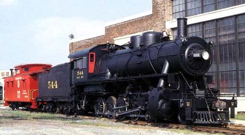
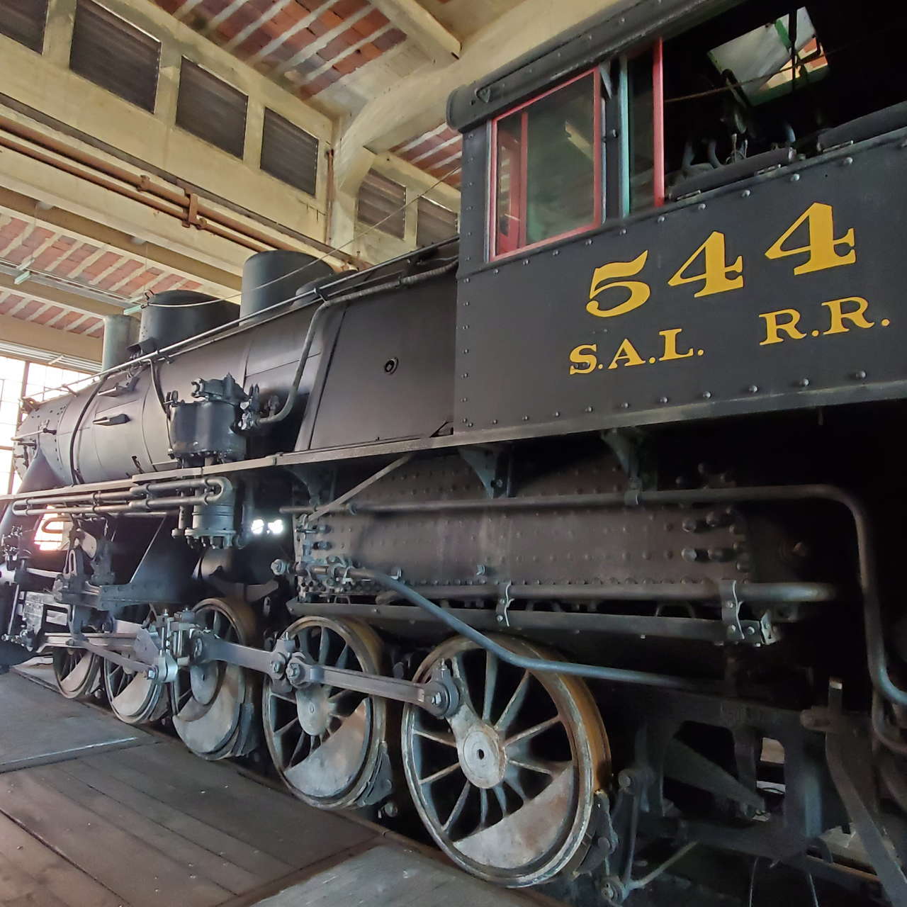
After the SAL took over the Georgia, Florida & Alabama's light decapods (see Locobase 1396) , they liked them so much they had Baldwin build eight more. They had 12" (305 mm) piston valves. Firebox heating surface area included 25 sq ft (2.3 sq m)
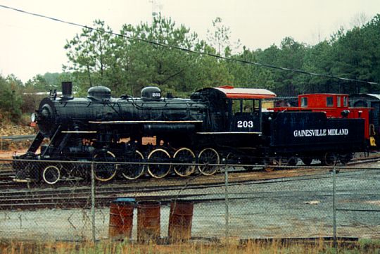
These were retired in 1952-1953, at which points several of both classes were taken up by Georgia's Gainesville Midland -- aka the Jug Tavern Route -- as their 203-209. The last of these was retired in 1959. The Durham & Southern received the 533.
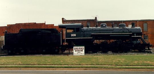
Some were put on display and data on their works # below comes from the SteamInfo listing ([], last accessed 4 July 2007).
Three were extant in 2007:
GM# Works # Date built
203 60342 January 1928
208 61230 March 1930
209 61233 March 1930
See the long article on restoring the 209 hosted on [], last accessed 6 July 2007.
See the quite detailed overview published by designer Alphonse I Lipetz, "Russian 'Decapod' Locomotives", The Railway Engineer, Volume 43, No 2 (February 1922), pp. 51-54; April 1922, pp. 136-137; July 1922, pp. 249-251; and November 1922, pp. 415-417. (Thanks to Chris Hohl for his 8 February 2019 email correcting the Russian decapods' wheelbases.)
857 2-10-0s were built by Baldwin and Alco (Richmond and Schenectady Works) for the Russian Government. When that empire was overthrown, some 200 more of the Russian order was diverted to railroads in the US by the USRA.
Langley and Beckum (in Drury (1993)) comment that the Seaboard liked them for much the same reason as other railroads that used these displaced engines. They were "ideal for logging and phosphate service on light-rail branches in Florida." After the initial 20, ten more came from the DT&I and eight others from the GF&A.
In response to a question fielded by the ([], accessed 4 February 2007), Lamar Wadsworth responded on May 30, 2000 that the 2-10-0s proved a good bargain: "the old Decapods (called "Russians") by most men on SAL) were versatile engines well suited to freight service on light rail and undulating terrain-- that's why Gainesville Midland bought a bunch of them secondhand from SAL and got good service out of them .... One very typical assignment for the Russians was in drag freight service pulling trains of iron ore from Cartersville GA to the junction with the SAL main at Rockmart. If you're familiar with the line (now a hiking trail) from Rockmart east, you know that eastbound SAL trains were "down on their knees" from the Rockmart depot up Braswell grade to the "easy spot" just before Divide Tunnel--my father said that a Russian would sometimes shove the rear of a freight on Braswell."
Ilustrations in Linn Wescott (Model Railroader Cyclopedia - Vol 1, 1960) and see Drury (1993), 176. Also see [] for 1929 locomotive diagrams. These give the higher weights used in the specifications.
| Principal Dimensions by Steve Llanso of Middle Run Media | |||
|---|---|---|---|
| Class | 400 | D-3 | D/D-1/D-4/D-5 |
| Locobase ID | 1396 | 1397 | 4402 |
| Railroad | Georgia Florida & Alabama (SAL) | Seaboard Air Line (SAL) | Seaboard Air Line (SAL) |
| Country | USA | USA | USA |
| Whyte | 2-10-0 | 2-10-0 | 2-10-0 |
| Number in Class | 6 | 8 | 34 |
| Road Numbers | 400-405 / 523-528 | 529-536 | 500-522, 540-550 |
| Gauge | Std | Std | Std |
| Number Built | 6 | 8 | 34 |
| Builder | Baldwin | Baldwin | several |
| Year | 1924 | 1930 | 1918 |
| Valve Gear | Walschaert | Walschaert | Walschaert |
| Locomotive Length and Weight | |||
| Driver Wheelbase (ft / m) | 19.67 / 6 | 19.67 / 6 | 18.67 / 5.59 |
| Engine Wheelbase (ft / m) | 28.25 / 8.61 | 28.25 / 8.61 | 27.83 / 8.39 |
| Ratio of driving wheelbase to overall engine wheelbase | 0.70 | 0.70 | 0.67 |
| Overall Wheelbase (engine & tender) (ft / m) | 59.99 / 18.28 | 60.87 / 18.55 | 60.29 / 18.38 |
| Axle Loading (Maximum Weight per Axle) (lbs / kg) | 38,000 / 17,237 | 38,000 / 17,237 | 38,000 / 17,237 |
| Weight on Drivers (lbs / kg) | 190,000 / 86,183 | 190,000 / 86,183 | 185,000 / 83,915 |
| Engine Weight (lbs / kg) | 212,000 / 96,162 | 212,000 / 96,162 | 207,700 / 94,211 |
| Tender Loaded Weight (lbs / kg) | 141,500 / 64,183 | 137,500 / 62,369 | 134,800 / 61,144 |
| Total Engine and Tender Weight (lbs / kg) | 353,500 / 160,345 | 349,500 / 158,531 | 342,500 / 155,355 |
| Tender Water Capacity (gals / ML) | 7000 / 26.52 | 7000 / 26.52 | 7400 / 28.03 |
| Tender Fuel Capacity (oil/coal) (gals/tons / Liters/MT) | 12 / 11 | 12 / 11 | 13 / 12 |
| Minimum weight of rail (calculated) (lb/yd / kg/m) | 63 / 31.50 | 63 / 31.50 | 62 / 31 |
| Geometry Relating to Tractive Effort | |||
| Driver Diameter (in / mm) | 56 / 1422 | 56 / 1422 | 52 / 1321 |
| Boiler Pressure (psi / kPa) | 190 / 1310 | 190 / 1310 | 180 / 1240 |
| High Pressure Cylinders (dia x stroke) (in / mm) | 24" x 28" / 610x711 | 24" x 28" / 610x711 | 25" x 28" / 635x711 |
| Tractive Effort (lbs / kg) | 46,512 / 21097.51 | 46,512 / 21097.51 | 51,490 / 23355.50 |
| Factor of Adhesion (Weight on Drivers/Tractive Effort) | 4.08 | 4.08 | 3.59 |
| Heating Ability | |||
| Tubes (number - dia) (in / mm) | 167 - 2" / 51 | 167 - 2.25" / 57 | 194 - 2" / 51 |
| Flues (number - dia) (in / mm) | 28 - 5.375" / 137 | 28 - 5.375" / 137 | 28 - 5.375" / 137 |
| Flue/Tube length (ft / m) | 17 / 5.18 | 17 / 5.18 | 17 / 5.18 |
| Firebox Area (sq ft / m2) | 197 / 18.30 | 197 / 18.30 | 227 / 21.10 |
| Grate Area (sq ft / m2) | 54.30 / 5.04 | 54.30 / 5.04 | 64.70 / 6.01 |
| Evaporative Heating Surface (sq ft / m2) | 2343 / 217.67 | 2343 / 217.67 | 2610 / 242.57 |
| Superheating Surface (sq ft / m2) | 553 / 51.37 | 553 / 51.37 | 579 / 53.81 |
| Combined Heating Surface (sq ft / m2) | 2896 / 269.04 | 2896 / 269.04 | 3189 / 296.38 |
| Evaporative Heating Surface/Cylinder Volume | 159.82 | 159.82 | 164.05 |
| Computations Relating to Power Output (More Information) | |||
| Robert LeMassena's Power Computation | 10,317 | 10,317 | 11,646 |
| Same as above plus superheater percentage | 12,277 | 12,277 | 13,742 |
| Same as above but substitute firebox area for grate area | 44,542 | 44,542 | 48,215 |
| Power L1 | 10,046 | 10,046 | 8781 |
| Power MT | 582.83 | 582.83 | 523.21 |