Just how sharp is that curve?
We all know that the curvature of railroad tracks is measured by its radius, right? Bzzzzt -- wrong! Well, not in the "real world" anyway. Prototype railroaders use a different measure of curvature than the modeler might use -- degrees. Wait a minute, isn't a degree a measure of angle? How can an angular measurement be used to specify curvature? Let's start by discussing curves on a model railroad.Model railroaders probably measures their curves by measuring the radius of that curve. This makes a lot of sense. It seems like a straight forward thing to do. We've all heard of 18 inch radius, 24 inch radius, and even O27 (27 inch diameter). To make a curve, one simply needs to determine the center of that curve, then use a nail, a piece of string, and a pencil to draw where the curve is supposed to go.
Because of the distances involved, in prototype railroads it would be impractical to measure a curve by its radius. Using the system we use in model railroad would put the center of curvature a great distance from the tracks. Instead, prototype railroads use degrees of curvature, or more precisely "degrees per chain", where a chain is an engineers chain (a unit of distance equal to 100 feet and traditionally measured with a chain).
Just to keep things confusing, land surveyors also measure distance in chains (and rods!), but a surveyors chain is not the same length as an engineer's chain!
Think of trying to survey a railroad line. You can't just stick a compass point in the ground at the center of the desired curve and scribe the centerline of the track, the sizes are just too large.
Instead, what is done is to work your way down the right-of-way pounding stakes into the ground every chain (100 feet!) to indicate where the centerline of the track belongs. The grading crew follows you and tries to make a level grade along the line you've surveyed (with the help of a leveling crew that uses different surveying instruments, specifically, levels), and then another survey crew follows, re-marking the centerline on the top of the grade for the tracklayers.
 |
| Figure 1 |
Of course, it gets more complicated on rough terrain but this is the general idea of laying out curves of a certain degree.
Now that we know how a degree is used to measure the curvature of a curve, some of you may want to know how to convert between degrees and radii. To convert from curves measured in degrees to the radius of the curve, we need to lay out some geometry and then do a bit of trigonometry.
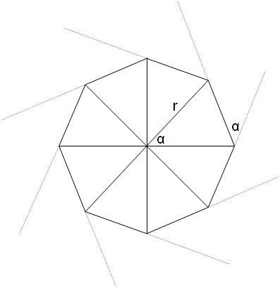
Figure 1 shows how an imaginary circle of 45 degree curvature might be
laid out. Each vertex on the surface of this circle represents where a
stake is located and where the endpoint of the 100 foot engineer's chain
begins and ends. Because 360 degrees divided by 45 degrees equals 8,
this curve would be created in 8 steps as described above. Figure 1
also shows where the center of this circle would be. "r", the radius of
this circle is also shown. Most importantly, notice that the angle of
each section as seen from the center of the circle is equal to the angle
of curvature as shown at each stake. If this does not seem intuitive,
consider a mental picture of a circle of 90 degree curvature.
 |
| Figure 2 |
r * sin(alpha/2) = 100/2.
or
sin(alpha/2) = 50/r
or
alpha/2 = arcsin(50/r)
or
alpha = 2*arcsin(50/r)
Here is a table showing a comparison of various curves.
| Degree Curvature | 100 ft Segments | Circumference (ft) | Radius (ft) | HO Radius (in) | N Radius (in) |
|---|---|---|---|---|---|
| 1 | 360.0 | 36000 | 5729.7 | 790.3 | 429.7 |
| 2 | 180.0 | 18001 | 2864.9 | 395.2 | 214.9 |
| 3 | 120.0 | 12001 | 1910.1 | 263.5 | 143.3 |
| 4 | 90.0 | 9002 | 1432.7 | 197.6 | 107.5 |
| 5 | 72.0 | 7202 | 1146.3 | 158.1 | 86.0 |
| 6 | 60.0 | 6003 | 955.4 | 131.8 | 71.7 |
| 7 | 51.4 | 5146 | 819.0 | 113.0 | 61.4 |
| 8 | 45.0 | 4504 | 716.8 | 98.9 | 53.8 |
| 9 | 40.0 | 4004 | 637.3 | 87.9 | 47.8 |
| 10 | 36.0 | 3605 | 573.7 | 79.1 | 43.0 |
| 18 | 20.0 | 2008 | 319.6 | 44.1 | 24.0 |
| 24 | 15.0 | 1511 | 240.5 | 33.2 | 18.0 |
| 36.4 | 9.9 | 1006 | 160.1 | 22.1 | 12.0 |
| 45 | 8.0 | 821 | 130.7 | 18.0 | 9.8 |
One benefit of surveying curves this way is that, if the track needs to make a total curve of, say, 10 degrees, as measured between the tangents at each approach to the curve, all you do to determine the number of surveying stations between the start of the curve and the end of the curve and divide the total curve by the number of degrees allowed as the maximum curvature. Thus, for the example 10 degree curve, if the maximum allowed curve is a 2 degree curve, then there will be 5 survey stations that must be offset by 2 degrees each to make the total curvature.
Approach spirals into tight curves can be worked out similarly. To start a 9 degree curve (that's pretty sharp), you might require one survey station at 3 degrees, one at 6 degrees, and then 9 degrees per station from there on into your spiral, and then work your way back to a tangent with a 6 degree step and a 3 degree step.
(This article was re-written from a discussion of this topic on a computer newsgroup called rec.railroad. A good portion of this information was posted by Doug Jones at the University of Iowa.)